Launcher Construction in Germany
My first launcher was built with parts from the German "Gardena" garden watering system. It is quick to build; but soon the main disadvantage bothered me: it requires a relatively heavy nozzle assembly, which brings the CG (center of gravity) of the rocket towards the nozzle end of the rocket.
So, quite soon I decided to build something more versatile. Reading about various launcher designs, the votes soon went to Paul Grosse's Copper Tube Launcher. One of the main advantages: you can launch all kinds of nozzle diameters. However, the parts listed on Paul's site were not available in Germany, so I adjusted the design to the available material.
![]()
Launcher details: bottles and o-rings
Adjustable launch tube and picture of total assembly
The launcher in action: Several videos (plus more on other pages) on this site.
![]()
Parts
From bottom to top you need (Cu=copper, Kupfer):
Amount |
English |
German |
OD (mm) |
ID (mm) |
1 |
Cu sleeve, bottom |
Cu Muffe, |
- |
28 |
15 cm |
Cu tube |
Cu Rohr |
28 |
|
1 |
Cu T-piece |
Cu T-Stück |
|
28 / 12 |
5 cm |
Cu tube, fitting |
Cu Rohr, in T- |
12 |
|
1 |
Cu cap |
Cu Kappe |
|
12 |
1 |
Bicycle tire valve |
Fahrradventil |
|
|
40 cm |
Cu tube |
Cu Rohr |
28 |
|
1 |
top Cu sleeve |
obere Cu Muffe |
|
28 |
10 |
cable ties, |
Kabelbinder, |
|
|
5cm |
plastic tubing |
Plastikrohr |
|
39 |
3 |
hose clamps |
Rohrschellen |
|
>30 |
3 |
adjustable |
einstellbare |
|
|
4 |
tent pegs |
Zeltheringe |
||
more |
strings |
|
|
|
1 |
small pulley |
kl. Umlenkrolle |
|
|
70+ cm |
PVC tubing |
PVC Rohr |
21 |
|
|
solder, flux |
Lötzinn, Flussmittel |
|
|
Description of assembly
The bottom sleeve was hard soldered to the 15cm tube by a friend of a friend with the necessary plummers' tools. The other copper parts and the bicycle valve tube I soldered myself with a camping gaz stove. Next time I would try to find a better heat source, since it was just barely hot enough for soldering. When I opened the window to let the vapors out, the little breeze from the open window was enough to inhibit any melting of the solder!
We have a German saying: "Ein Bild sagt mehr als 1000 Worte", so let's continue
with pictures, from bottom to top
 |
Bottom sleeve of the launcher with pulley for the red-blue trigger string.
The concave bottom of the launcher is set on top of a tent peg. |
|
|
Over time, the tied-up pulley from above was replaced by a fixed one, as shown here. |
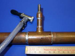 |
Air inlet of the launcher. The bicycle valve tube is soldered into the
12mm Cu cap.
NO VALVE is inserted HERE: one must be able to depressurize the rocket from a distance in case something goes wrong.
|
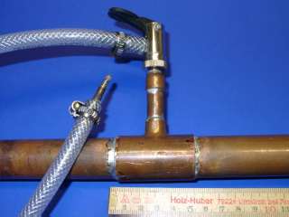 |
Air inlet with air hose attached.
The other end of the air hose (bottom left) has a bike valve glued in. |
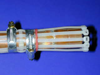 |
Top section of launcher.
The rightmost Cu part is the sleeve with 28mm ID, ideal for pop bottles. The cable ties are attached with 2 hose clamps; they run above another cable tie between the clamps to increase the friction. No glue of any kind is needed. |
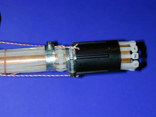 |
Top section with trigger ring. Drill three holes into the trigger ring to fasten three trigger strings. They are united into one string which is fed through the pulley at the bottom of the launcher. |
Launcher details: bottles
 |
Bottle mouth with o-ring.
This position of the o-ring is much better than between the 2 flanges (a little more to the right), as described elsewhere. |
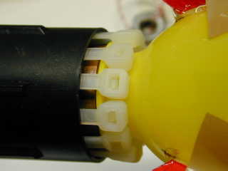 |
Detail: rocket in launcher, trigger ring down. |
 |
Detail: rocket in launcher, trigger ring up. |
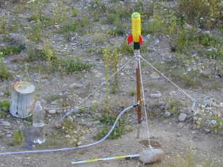 |
Launcher with small rocket, ready for start.
One tent peg was replaced with a stone. |
Launcher details: adjustable launch tube (LT)
 |
Launcher with launch tube. |
|
Assembly of launcher with adjustable launch tube.
The details 7 and 8 did not always prove functional. Some air was still escaping sideways, or the launch tube was still shot out of the launcher. They were replaced by: |
|
|
Left: I drilled a couple of holes into the LT with 2 cm distance. Then, after the LT is inserted into the launcher, a 4 mm beheaded nail is pushed into the horizontal air inlet, all the way in, through the holes, anchoring the LT very solidly in the launcher. Right: the yellow taped region is a well fitting
gasket to seal the space between LT and the inside of
the launcher. Thus, no air gets lost any more during
start, all air must escape through the inside of the
LT (lower end open) into the rocket, as long as it
has not left the LT. |
The PVC tubes available in Germany (20.5 mm OD) for launch tubes as they are do not give a tight fit to the bottle mouth. Covering it with self adhesive foil (used for books otherwise) gives a nice snug fit inside the bottle.
In action
 |
Note that the launch tube is not secured enough inside the launcher: it is pulled out of the launcher and falls back in. (This was the first version, when neither the o-rings (7, 8 above) nor the nail fixation were invented.) In summer 2000, when launching from a sailboat, I lost a launch tube this way (it sank faster than I could dive after it ...). |
![]()


